
Frequently asked questions
On this page we answer frequently asked questions about RasaAndishan cameras. Most of them are about line scan cameras, lens choice, line rate and resolution. If you cannot find your answer, ask us through the Contact us page.
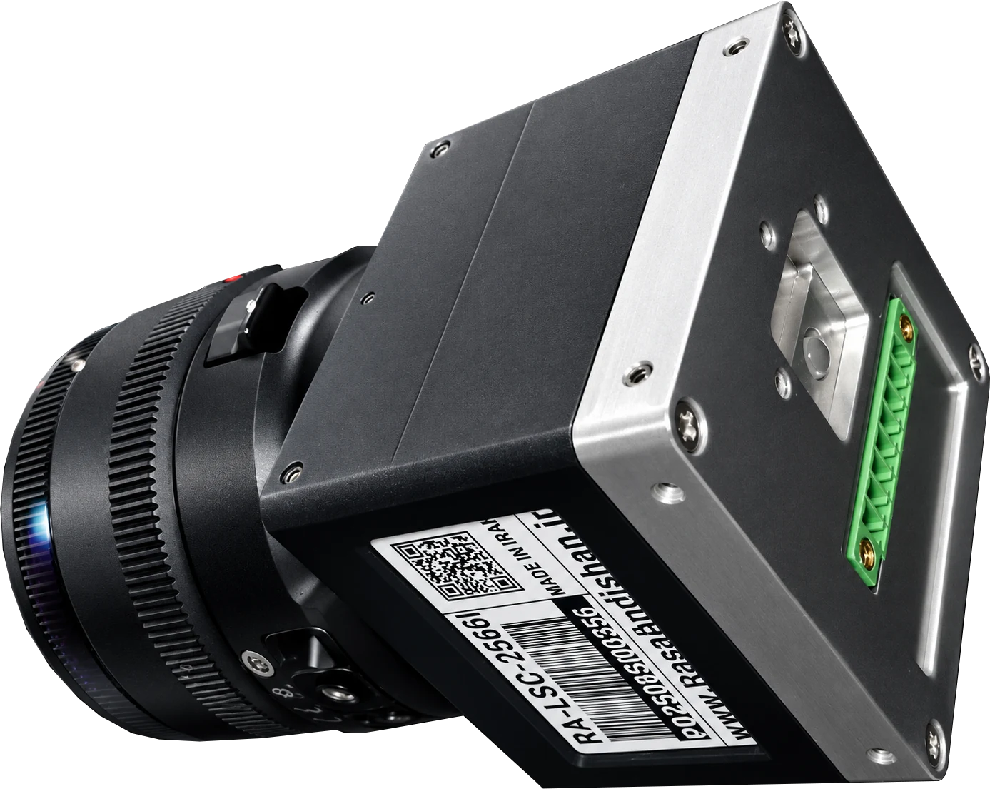
Line scan camera FAQ
Models and specifications are on the line scan camera page. For the basics of this technology, read the Wikipedia article on line scan cameras.
One concern with any camera, especially industrial cameras, is choosing the right lens for the location and the task. Choosing the right lens to zoom and focus on a specific part of the scene matters a great deal. Suppose you use an extremely professional camera with very high resolution. Even then, if the lens does not deliver suitable light to the CCD, the CCD cannot produce a good image. The reason is that all the light reaching the CCD passes through the lens. If the lens is unsuitable, it changes the properties, refraction, and behavior of the light passing through it. As a result, the CCD produces a poor image from bad input. After choosing a lens of good quality, the next step is choosing a lens with the right angle of view and depth of field. Another important point in choosing a lens is the right focal length. The focal length of a lens sets the angle of view. The larger this number (in millimeters), the narrower the angle of view, and the larger distant objects appear. The smaller it is, the wider the angle of view. Depth of field is set mainly by the f-number and the magnification; at the same distance, a telephoto lens has less depth of field than a wide-angle lens. A wide lens is chosen for its wide angle of view, and a TELE lens (long focal length) for seeing distant objects with a narrow field of view. Every lens has a part called the iris, which adjusts the light passing through the lens (in different environments and at different times of day). In some lenses, the iris adjusts automatically (Auto iris). Cameras that use these lenses deliver a perfectly clear image at all hours of the day. In other lenses, you have to set the iris by hand (manual iris). Cameras with these lenses give a sharp, clear image only in the light level the iris was set for. If the light changes, the image drifts away from normal to the same degree. An important point in choosing a camera is its field of view. The field of view is set by two factors: the focal length (Focal length) and the size of the image sensor (Image sensor). Focal length is the distance from the lens's focal point to the point where light enters the lens. The focal point is the point where all the light entering the lens converges. The longer the focal length, the narrower the field of view. The best and fastest way to choose the focal point and focal length is to use one of the calculators available for this (as a ruler or a computer program).
Dynamic range is one of the key measures of signal sensitivity. Dynamic range is defined as the ratio of the maximum pixel capacity in electrons to the RMS noise in electrons. You can also express this number in decibels (base 10). In practice, this ratio is the difference in brightness between the darkest and brightest areas of an image that still show distinguishable detail. In some images, some dark or bright areas have detail and others have no distinguishable detail or texture. The dynamic range of an image tells you what range of brightness the image holds, from the darkest parts that contain detail to the brightest parts. The larger this range, the greater the image's dynamic range. In such an image, more of the dark and bright areas show distinguishable detail. The dynamic range of a CCD (in dB, decibels) is given by the following formula:
Dynamic range (dB) = 20·log(signal voltage at saturation ÷ RMS dark noise voltage)
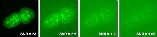
To obtain a better image, the dynamic range should be as high as possible. The lower limit of the dynamic range of an imaging system is set by noise. The figure below shows how dynamic range affects image quality.
In the design of CCD driver circuits there are two categories of noise: noise from the CCD itself and noise from the CCD readout circuitry.
This noise is generated inside the CCD sensor and appears in its output signal. It includes:
- Reset noise: a form of thermal noise associated with the resistance of the sense node (the transistor gate that converts the charge collected in the CCD into a voltage).
- Shot noise: this noise is due to the random motion of electrons as they arrive at the sense node. Because shot noise stems from the inherent, natural motion ofelectrons, it cannot be eliminated.
- Dark noise: This noise comes from electrons generated by heat in the CCD, and it is always one of the main noise challenges in a CCD. Dark current sources depend strongly on temperature, so the best way to reduce this noise is to cool the CCD. How much you need to cool the CCD depends largely on the longest integration time you want and the lowest acceptable signal-to-noise ratio.
- Pixel non-uniformity noise: In practice, it is impossible to build a CCD whose pixels are all exactly identical. Quantum efficiency, impurities, and charge traps are not the same in every pixel. So pixels produce different voltages even at the same light intensity and exposure time. To correct this difference, take an image of a perfectly collimated light source of uniform intensity and build a pixel difference matrix from it. First subtract the dark frame from each image, then divide it by this gain matrix. This method is called flat field correction (Flat Field).
- Dark current non-uniformity noise: All pixels generate dark noise electrons because of heat. But since the pixels are not identical, the number of these electrons differs from pixel to pixel. To correct this, take an image with the CCD in complete darkness. Then subtract this image, as a matrix, from the images the CCD captures. This software technique is called dark frame subtraction.
CCD readout circuit noise
In addition to CCD noise, the electronic and driver circuits outside the CCD naturally also introduce noise, including:
- White noise: a form of thermal noise caused by the resistances at the CCD output node. The best way to reduce it is to lower the temperature. It can also be reduced by increasing the capacitance of the CCD output node.
- Flicker noise: this noise arises in digital circuits in which components are continually switching on and off.
- Analog-to-digital conversion noise: In any digital system, quantizing analog voltages discards some information. In the CCD readout circuit, this information is the CCD output voltage. This voltage represents the color or light intensity of each CCD pixel. Losing this information causes image defects; this defect is called ADC noise.
Integration Time: the time it takes to scan one Line. Exposure Time: the actual time the CCD is exposed to light during the scan of one Line. Exposure Control: some line scan cameras have a mechanism that lets you reach Exposure Times shorter than the scan time of one line. This mechanism is called an electronic shutter.
On the website, above the models table, you will find the CCD's pixel specifications, maximum line rate, and effective length. These figures are the same for all models of this camera because they all use the same CCD. The other parameters depend on each model's hardware and vary from model to model. For example, the pixel size of this camera is 200X14 microns in all models. But the resolution of each pixel depends on the camera hardware.
The focal distance depends on the lens you use, and the choice of lens in turn depends on the distance from the camera to the object and the object's length. Since you supply the lens yourself, our cameras have an adjustable mechanism that sets the distance between the lens and the CCD so you can reach the right focus. To calculate the lens, click the link opposite. Lens Calculator
In monochrome cameras with an analog output, you can command the camera to send the light intensity of a specific pixel to its analog output. For example, through the software you can continuously watch the light intensity of pixel number 1350 on a scope. The maximum light intensity at this pixel corresponds to 4 volts and the minimum to zero volts. In color cameras with an analog output, you can command the camera to send the red, green, or blue light intensity of a specific pixel to its analog output. For example, through the software you can continuously watch the red intensity of pixel number 1350 on a scope. The maximum red intensity at this pixel corresponds to 4 volts and the minimum to zero volts.
The FOV, or field of view, has nothing to do with the speed of the object. Resolution in the direction of motion depends on the camera's line scan rate. Assume the object does not distort in the X and Y directions and keeps its direction of travel exactly. In that case, two things set the minimum line rate: the maximum speed of the object and the minimum imaging resolution you need on the object.
Example 1: Calculating resolution across the width of the belt (perpendicular to the direction of motion)
Conveyor belt width: 550 mm
Resolution in the direction of motion: 0.3 mm per pixel
Number of pixels needed: simply divide the belt width by the resolution. So at least 1833 pixels are needed for imaging. Typical line scan camera resolutions are 512, 1024, 2048, 2700, 3648, 4096, 8192, 10680, and 12288 pixels. So the minimum resolution for this application is 2048 pixels or more. With a 2048-pixel camera, the imaging resolution is 0.27 mm per pixel.
Example 2: Calculating the line scan frequency
For a maximum object speed V, field of view FOV, pixel width W and effective sensor length S, the minimum line readout frequency FL is:
FL= (V * S) / (W * FOV)
In other words, which customer requirements can you customise on the cameras?
The hardware program (firmware) of our P-model cameras can be modified to suit customer requirements. Suppose, for example, that a specific filter is needed to smooth the pixel data, and so on; in that case the P model makes this possible for the customer. If the existing hardware lacks the necessary capability, we will design new hardware to meet our customers' requirements.
This source code is essentially a demo program that lets your computer communicate with the camera. Foreign camera makers provide DLL files, an API, and the command set needed to communicate with the camera. The source code on our website gives customers all of these in one place. In the demo software, the user sends the camera the start-streaming command and the gain, offset, exposure time, and other settings. The camera sends the software the light intensity of every pixel, from pixel 1 to pixel N, along with the frame rate and line read rate, in one frame.
You can use your computer's other ports to send commands to other control systems. For example, the camera data reaches you over USB. After processing this data, you can send the command you need to other systems over Ethernet. But if you want a specific command to go to an external actuator through the same USB port that is connected to the camera, the camera hardware needs to be customized for you.
Let us explain the concept of exposure time with an example.
Suppose the CCD surface is fully covered except for a single 0.5 mm slit placed perpendicular to the CCD at a short distance. If you set the exposure time to 100 microseconds, you get image number 1. If you set it to 1 millisecond, you get image number 2.

Exposure time: 100 microseconds

Exposure time: 1 millisecond
As the figures above show, the longer the exposure time, the more pixels are exposed to light from neighbouring pixels. In both images, the CCD pixels at the centre of the slit are saturated (blooming). If we reduce the exposure time, these pixels come out of saturation.
Exposure time is inversely related to line rate. That is, the longer the exposure time, the lower the rate at which lines are read from the CCD. At low light levels, you should increase the exposure time. At high light levels, you should reduce the exposure time so the CCD does not saturate. So you can say that this camera's electronic exposure time does the same job as the aperture or mechanical shutter in other cameras.
The difference between these cameras and area scan cameras is that, in a given exposure time, these cameras read only one line, not a 2D area. So in applications where both the light source and the object are fixed, the exposure time of these cameras will depend on how fast the light intensity changes.
There are two ways to do this. The first is to measure with a tape and photograph a subject at two different distances from the lens. It sounds simple, but for a usable result you need very precise tools and a tidy setup.
In short, you take two photos of a subject. Then you calculate the magnification from the resulting images; for example, you can measure the photos in Photoshop and work out the ratio. We call this ratio m. Next you find how far the subject had to move to produce this magnification; that is, you measure the subject-to-sensor distance twice. We call this value Δd. Finally, the focal length follows simply from this relation:
However, this measurement requires precise measuring tools, because an error of one centimetre in the tape can change your Δd by as much as 20 millimetres!
The second way is better and more sensible. Photograph a subject that has two well-defined points at infinity, with the focus set to infinity. If you know the angular separation of these two points (we call it θ), then:
Measuring the distance between two points in Photoshop is easy. The number just has to be the exact distance on your sensor. The simplest way is to count the pixels between the two points in Photoshop (if you have the coordinates of the two points, basic analytic geometry gives you the distance just as easily). Then convert those pixels to a real length using the sensor specifications. For example, divide the sensor length by the number of pixels along it, work it out from the sensor area, or use the pixel size published by the manufacturer; if that value is in microns, convert it to millimetres, and so on.
The number 57.2957795 is simply 180 divided by pi, which converts degrees to radians; that leaves θ itself. Calculating θ is simple. If you capture the image at infinity focus (that is, 3 to 5 metres away), tan θ is almost equal to θ. It equals half the object's length divided by the distance from the object to the camera.
More questions about industrial cameras
Practical answers from the engineers who design and build the cameras. Click a question to open it.
Choosing a camera
Line scan when the object moves continuously (conveyor, web, sheet, pipe) or is cylindrical and must be “unrolled”; area scan when the part is stationary and fits in one frame. Line scan gives seamless, endless images with simple line lighting; area scan is easier to set up and needs no encoder.
Choose colour only when colour itself is the information (print inspection, colour sorting, coloured wires). Otherwise monochrome is more sensitive, more accurate and cheaper, and needs less light. Our tri-linear colour cameras read each pixel in three separate channels, so unlike a Bayer filter no resolution is lost.
Divide the field-of-view width by the smallest detail you must see, then multiply by 2–3 for safety. Example: 550 mm width and a 0.3 mm defect → 1833 pixels → with margin, a 4000–5000 pixel model. The full calculation with examples is in our article on line rate and resolution.
Divide the object speed by the size of one pixel on the object. For 2 m/s and a 0.3 mm resolution you need about 6667 lines per second. If the speed varies, trigger from an encoder instead of a fixed rate.
CCD offers lower noise, better pixel-to-pixel uniformity and a more linear response, which suits measurement, spectroscopy and low light. CMOS offers very high line rates and lower cost at very high resolutions. RasaAndishan cameras are built on both CCD and CMOS sensors and are optimised for measurement and inspection at medium to high speeds.
For most inspection lines, yes. USB 2.0 offers about 480 Mbit/s and USB 3.0 up to 5 Gbit/s; a 5000-pixel, 8-bit camera at 1000 lines/s produces only 40 Mbit/s. The main limit of USB is cable length (3–5 m without a repeater); use an active cable or an industrial hub for longer runs.
Larger pixels collect more light, are more sensitive and less noisy; smaller pixels give more resolution for the same sensor length. Pick large pixels (e.g. 14 µm) for low light, high speed or spectroscopy, and small pixels (5–7 µm) for fine measurement with enough light.
Lens and lighting
The lens image circle must cover the whole sensor length: C-mount is enough for sensors up to about 28 mm; longer sensors (40 mm and above) need F-mount or M42 lenses. Focal length ≈ working distance × sensor length ÷ field of view.
f = D × S ÷ FOV, where D is the camera-to-object distance, S the active sensor length and FOV the field-of-view width, all in mm. For 1 m distance, 28 mm sensor and 550 mm FOV, f ≈ 51 → a 50 mm lens. A fuller answer with examples is at the top of this page.
Two common causes: the lens is too small for the sensor length (vignetting) or the aperture is wide open. Stop down one or two f-stops, use a lens with a larger image circle, and run flat-field correction in the software against a uniform white reference.
An LED line light that illuminates only the camera's line of view. For glossy surfaces use low-angle or diffuse light; for edge measurement use a backlight; for surface defects use dark-field light at a very low angle. The light must be flicker-free (DC or very high frequency), otherwise bright and dark bands appear in the image.
Stop the aperture down (f/8 instead of f/2.8) and add light, increase the working distance with a longer focal length, or if the object height varies use a telecentric lens, whose magnification does not change with distance.
The LED supply flickers (PWM or mains) and is sampled at the camera's line rate. Use a constant-current DC driver or push the PWM frequency above 20 kHz. Fluorescent tubes always cause this — keep them out of the field of view.
Installation and set-up
The camera's line of view must be perpendicular to the direction of travel, and the lens perpendicular to the surface. Put a ruler or a chequered sheet on the belt and move it in the live view: skewed or stretched lines mean the camera is rotated. Our software's line-scope view makes this alignment a one-look job.
Not if the line speed is constant — a fixed line rate is enough. Yes if the speed varies or the line stops and starts: the encoder gives one pulse per fixed travel distance and the camera captures one line per pulse, so the image scale always stays correct.
USB 2.0 up to 5 m and USB 3.0 up to 3 m with a passive cable. Beyond that, use an active cable (15–20 m) or an industrial powered hub. Cheap cables drop lines at high speed; use shielded cables with screw locks.
In order: change the cable and plug directly into a rear port (not a front hub); install the driver from the CD or our site; check Device Manager for a yellow warning; disable “USB selective suspend” in Windows power settings.
The camera has an isolated trigger input that works with a photo-sensor, PLC or encoder (5 V or 24 V, per order). Set the trigger mode to external in the software and choose the rising or falling edge. Separate inputs are provided for frame start and line start.
Two usual calibrations: (1) flat-field correction with a uniform white reference under the camera, to cancel pixel sensitivity differences and edge fall-off; (2) dimensional calibration with a ruler or a pattern of known spacing, so the software knows how many millimetres one pixel is.
Image quality and troubleshooting
Blur across the width is focus or aperture; blur only along the direction of travel means the exposure is too long for the speed — shorten exposure and add light, or raise the line rate. Rule: the object should move no more than one pixel per line.
Pixels with slightly different sensitivity, or dust on the sensor window. Re-run flat-field correction with a clean white reference and clean the lens and sensor window with a blower and a microfibre cloth — never with fingers or ordinary tissue.
Bandwidth or CPU is running out: change the USB cable and port, close other programs, increase the read buffer in the software, and reduce resolution or line rate if possible. Our software shows a “Lost Lines” counter; if it is not zero, one of these is the cause.
The ratio between the brightest and darkest things the camera can record at the same time without saturating or drowning in noise. The higher it is, the better dark and bright areas are seen together. A 16-bit converter and large pixels raise dynamic range; the full explanation is at the top of this page.
A metal body at 40–50 °C in a warm environment is normal; the body is dumping sensor heat. If ambient is above 45 °C or the camera sits in a closed enclosure, add an aluminium plate or a small fan. Excess heat raises noise and shortens life.
Software and integration
RasaAndishan's own software (ALTRON) with Persian and English UI: live view, line scope, exposure and gain, triggering, calibration, image and video saving. For programming, a DLL library with C++, C# and Python sample code is supplied.
Yes. The raw image is delivered in memory through the DLL and can be passed to an OpenCV array, a MATLAB matrix or a LabVIEW array. Sample code for all three is in the SDK package.
For visual inspection and most defect algorithms 8-bit is enough and faster. For intensity measurement, spectroscopy or high-contrast scenes, capture 16-bit (or 12-bit on the relevant models) so dark detail is not lost.
Usually 2–4 on USB 3.0 depending on resolution and rate; connect each camera to a separate USB controller (rear ports or a PCIe card) so bandwidth is not shared. Our software supports several cameras at once with a common trigger.
Buying, warranty and support
Yes. Model-selection advice is free, and we are glad to help you find the right model for your work. You then pay for the camera and have two weeks to test it under your own working conditions. If the camera does not suit your work, simply send it back to us; once we receive it, we refund the full amount.
Every camera has a three-year unconditional warranty. After that, repairs and upgrades continue in-house, because the cameras are designed and built in Iran.
Yes — that is the advantage of a local manufacturer. Spectral filter, cable length, interface, line rate, housing, software and even the processing algorithm can be adapted. Our photo-finish system and seam-tracking system were born exactly this way.
Popular models are usually in stock; customised models take a few weeks depending on the changes. Contact us for the exact time for each model.
Yes. Installation and user manuals in Persian, SDK sample code, and on-site or online training for operators and programmers come with the camera. Later questions go straight to the engineer who designed the camera.