
3648-pixel linear CCD detector, model RA-LSC-1304
The RA-LSC-1304 linear detector is a 3648-pixel monochrome linear CCD detector. It is highly sensitive, has an electronic shutter, and runs at 270 Hz. You can use it for spectroscopy or spectrometry. The RA-LSC-1304 detector has been designed and built in four versions. You can find the spectral response, parametric specifications, and full specifications further down this page.
Selection guide
Raman and fluorescence spectroscopy and very weak light
If your spectrometer works with weak signals, this is the camera we built for it. The RA-LSC-1304 is a CCD line-scan camera with 3,648 pixels, each 8 μm wide and 200 μm tall. Spread the 350 to 1000 nm band across its 29.184 mm array and each pixel sees about 0.18 nm of the spectrum. Exposure time can be set as long as 71 minutes.
- Sensor
- Linear CCD Array
- Effective pixels
- 1 × 3648
- Pixel size
- 8 μm × 200 μm
- Active length
- 29.184 mm
- Line rate
- 270 Hz
- Spectral range
- 350 nm to 1000 nm
- Dynamic range
- 300
- ADC resolution
- 16 bit
- Minimum exposure
- 1 μs
- Maximum exposure
- 71 min
The 3,648 pixels sit 8 μm apart over 29.184 mm. Spread a 650 nm band across the whole array and each pixel covers about 0.18 nm. The 200 μm pixel height catches the full slit image, so vertical alignment of the spectrometer is far less critical.
Raman and fluorescence signals are usually very weak. Each pixel has 1,600 μm² of area, and with exposures of several minutes even a faint signal rises to a level the converter can read. The -P and -I versions use a 16-bit ADC, so intensity differences between closely spaced peaks are recorded properly.
For sources that give off very little light, set the exposure as long as 71 minutes, in 1 μs steps. Offset can be shifted in 512 steps up to ±300 mV to keep the dark level inside the converter range.
Sensitivity starts at 350 nm, so you get part of the near-UV along with the visible range. The shortest exposure is 1 μs, short enough to record the reference spectrum of a bright lamp without saturation. At 270 lines/s you can take several spectra in a row and average them.
Because each pixel is 200 μm tall, the laser line stays on the array even if it drifts up or down a little. The laser light usually falls on several pixels, and computing the intensity centroid gives its position more precisely than 8 μm. Each line takes 3.7 ms, which means 270 independent readings per second.
For a teaching spectrometer the microcontroller version, -S, is enough: an 8-bit ADC, 12 μs to 65 ms exposure and 68 lines/s. Windows and Linux drivers and sample code for Matlab, LabVIEW, C++, C#, VB.Net and Python come with the camera, so students can get started right away.
The pixels are 25 times taller than they are wide (8 μm × 200 μm). The 8 μm width sets how finely you see the spectrum, and the 1,600 μm² area sets how sensitive the camera is to light. You get high spectral resolution without giving up sensitivity. With 3,648 pixels and a 650 nm band, each pixel sees about 0.18 nm, so closely spaced peaks show up separately. 270 lines/s is enough for process monitoring and averaging, and the 1 MHz pixel frequency puts little load on the computer. The dynamic range is 300:1, and the 16-bit ADC in the -P and -I versions covers it fully. Exposure can be set from 1 μs to 71 minutes in software, but since the sensor is not cooled, dark current fills the pixels in exposures of several minutes, so shorter exposures work better in practice; so the same camera handles both very bright and very weak light.
In a spectrometer, choose the grating so the band you need fills the full 29.184 mm of the array. If you use a lens instead, the focal length is roughly working distance × 29.184 mm ÷ field-of-view width. For a bright source, bring the exposure down to 1 μs; for a weak one, raise it to several minutes. There are four versions. The -P is the most complete: FPGA, 16-bit ADC, 480 Mbit/s USB, analog output, on-board RAM, a lens, a casing of your choice and customizable firmware. The -I has the same hardware without the lens, casing or firmware customization. The -A has a 12-bit ADC and 12 Mbit/s USB, with no analog output or RAM. The -S uses a microcontroller and an 8-bit ADC and is limited to 68 lines/s, 12 μs to 65 ms exposure and 0 to +65 °C. The other three versions run from -25 to +65 °C.

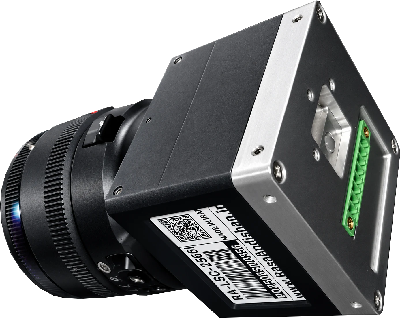
| RA-LSC-1304 USB Line Scan Camera Parameters | Specification |
|---|---|
| Sensor | Linear CCD Array |
| Pixel Size | 8 μm x 200 μm |
| Pixel Distance | 8 μm |
| Line Width | 200 μm |
| Effective Pixels | 1X3648 |
| Active Length | 29.184 mm |
| Spectral Range | 350 nm to 1000 nm |
| Max Pixel Frequency | 1 MHz |
| Dynamic Range | 300 |
| PGA Gain Resolution | 6 V/V - 64Steps |
| Programmable Offset Resolution | 300 mV - 512Steps± |
| Power consumption | 1.5 W |
| External Power | Not Required |
| Operational Temperature Range | −25 to +65 °C |
| Operation Systems | Windows 64-bit And Linux |
| Communication Port | USB2.0 Port |
| Multiple Cameras | Supported |
| Device Driver | Yes |
| Sample Codes | Matlab,LabView,C++,C#,VB.Net,Python |
| Camera Selection Guide | RA-LSC-1304-P | RA-LSC-1304-I | RA-LSC-1304-A | RA-LSC-1304-S |
|---|---|---|---|---|
| Processor | FPGA | FPGA | FPGA | MicroController |
| Gain Adjust | ✓ | ✓ | ✓ | ✓ |
| Offset Adjust | ✓ | ✓ | ✓ | ✓ |
| ADC Resolution | 16 bit | 16 bit | 12 bit | 8 bit |
| USB Speed | 480Mbit/S | 480Mbit/S | 12Mbit/S | 12Mbit/S |
| Analog OutPut | ✓ | ✓ | ✗ | ✗ |
| On Board RAM | ✓ | ✓ | ✗ | ✗ |
| Exposure Min | 1 μs | 1 μs | 1 μs | 12 μs |
| Exposure Max | 71 min | 71 min | 71 min | 65 ms |
| Exposure Resolution | 1 μs | 1 μs | 1 μs | 4 μs |
| Line Rate | 270 Hz | 270 Hz | 270 Hz | 68 Hz |
| Lens | ✓ | ✗ | ✗ | ✗ |
| Casing Model | Selectable By Customer | ✗ | ✗ | ✗ |
| Operational Temperature Range | −25 to +65 °C | −25 to +65 °C | −25 to +65 °C | −25 to +65 °C |
| Availability | 3Days After Order | 3Days After Order | 3Days After Order | 3Days After Order |
| Firmware Customizable | ✓ | ✗ | ✗ | ✗ |