
Article
Trigger Delay and Pulse Division on the Production Line with ALTRON
Suppose you mounted the part-detection photoelectric sensor a few centimeters ahead of the camera's field of view, because there was no room for it under the camera. The sensor sees the part, sends a pulse, and the camera captures an image immediately. The result? An image of an empty belt, or half a part. The solution is a trigger delay, so the camera waits briefly after the pulse arrives.
Why isn't the sensor always under the camera?
In practice, the detection sensor rarely sits exactly on the camera's line of sight. The lighting, the mounting frame or the camera housing takes up the space. So the sensor is mounted further ahead, and you compensate for the distance with time.
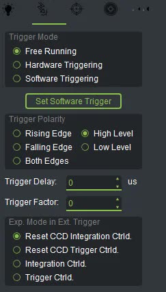
This setting is in the Trigger tab of the camera panel. On a line scan camera it is called Trigger Delay. On an area scan camera it is called Trig. in Delay. Its unit is microseconds, and it sets the time between the arrival of the pulse and the start of exposure.
The calculation is a simple division: divide the distance from the sensor to the field of view by the speed of travel. For example, if the distance is 5 cm and the belt moves at 0.5 m/s, the time needed is 0.1 s, or 100000 microseconds.
Enter this value, then fine-tune it by looking at the image. If the part has not yet fully entered the frame, the image was taken too early; increase the delay. If the part has already passed the middle of the frame, the image was taken too late; decrease the delay.
Keep one limitation in mind: a time delay is only accurate when the belt speed is constant. If the line speed changes, you must recalculate this value too.
With line scan cameras, triggering from an encoder is common. The encoder sends one pulse for each fixed amount of belt travel. This ties the spacing of the scan lines to the motion. So if the belt slows down or speeds up, the image is not stretched or compressed.
Sometimes, however, the encoder sends more pulses than you need. Trigger Factor divides the trigger frequency. For example, if you set it to 2, one image is taken for every two pulses. Its range is 0 to 255. So if the input pulse rate is very high, you do not need to replace the encoder; you thin out the pulses with this setting.
- In the Trigger tab, set the mode to Hardware Triggering and choose the Trigger Polarity that matches the sensor or encoder output.
- Press Rst Trig Counts in the camera panel to reset the counter to zero.
- Start the belt and check in the Diagnostics tab whether Trigger Counter increases.
- If you are using an encoder, compare Trigger Rate with the line rate you need. Then set Trigger Factor so that the trigger rate comes close to the required rate.
- Calculate the delay from the distance and speed, and enter it in Trigger Delay.
- Run a few parts through and check where each part sits in the image. Adjust the delay up or down until the part sits in the right place in the frame.
For an overview of the different models, see the line scan cameras.
A short general reference on rotary encoders: Wikipedia (English).
If the sensor and encoder layout on your line is more complex than this example, write to us through contact page and we will work it out together.