ALTRON Virtual Camera: working without hardware using test image patterns
rahni
You don't need to wait for a camera to arrive to learn ALTRON. The ALTRON virtual camera is a purely software camera that generates test image patterns and sits in the graph exactly where a real camera would. You can build and test the entire processing chain without a single physical camera.
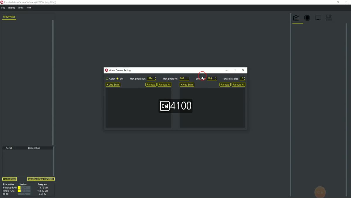
The Virtual Camera Settings window for creating a virtual camera in ALTRON
We use it a lot ourselves: when we build a new graph, when we want to see how a plug-in behaves on predictable data, or when a customer's software team writes code before the hardware is delivered.
Creating a virtual camera
In the main window, press the Manage Virtual Cameras button to open the Virtual Camera Settings window. The form is step-by-step; the next step isn't enabled until you make a choice in the previous one:
Camera type: choose either Area scan or Line scan. A line-scan camera delivers only one line at a time.
Pixel format: for an area-scan camera, BW8, BW16 and Bayer are available. Color on an area-scan camera comes from the Bayer mosaic and is debayered in the graph. For a line-scan camera you have RGB8, RGB16, BW8 and BW16.
Pattern: Choose the image pattern; we describe them below.
Resolution: Enter the width and height, or press one of the three shortcuts 200×200, 640×480 and 1920×1080. Height only applies to an area scan camera.
Emit Rate: the data generation rate: frames per second for an area-scan camera and lines per second for a line-scan camera. The default is 25 frames and 1000 lines per second.
Add camera Press it. The camera appears next to the connected cameras with a new serial number starting with 0000V.
The Remove button deletes the selected camera, and Remove All clears all virtual cameras at once.
Eight image patterns and what each is for
1 Gaussian: a soft, bright spot in the center of the image; on a line-scan camera, a bump in the middle of the line. Useful for seeing how plugins behave on a simple, symmetric shape.
2 Ramp: a linear ramp from zero at the left edge to the maximum value at the right edge. For checking levels, lookup tables and bit depth.
3 Color bar H and 4 Color bar V: Horizontal and vertical colour bars. They are only available with a colour format (RGB or Bayer) and are used to test the colour chain.
5 Static grad H and 6 Static grad V: a fixed horizontal and vertical gradient. On a line-scan camera, the vertical gradient advances in the scan direction and repeats from the start each time the number of lines reaches the image width.
7 White noise: random noise across the full value range, independently for each pixel. For load testing and trying out noise filters.
8 Moving gradient: the default pattern; a gradient that keeps moving across the image so you can see the image updating with your own eyes.
There is also a ninth pattern, Spectrometer, which simulates an emission line spectrum. Because it has its own settings, we cover it in a separate article.
Common mistakes
Colour bars in a monochrome format: The Color bar patterns are disabled with BW8 and BW16. If the selected pattern doesn't match the format, Moving gradient is selected automatically. So if you see a moving image you didn't expect, check the format.
Emit Rate set too high: Very high rates can fill up the processing queue. Unless your goal is load testing, start from the default.
Changing settings after Add: This form sets the settings of the next camera. If you want to change a camera you've already created, remove it and add it again.
A practical tip
Combine the White noise pattern with a high Emit Rate and watch the Performance tab. Without any production line running, you can see which node in your graph falls behind under load. When the real camera arrives, you only swap the camera node and the rest of the work is ready. To get to know the software itself, see the ALTRON.