
Article
Line Cropping, Line Reversal and Custom AOI in ALTRON
Why process and save pixels that nobody looks at? In many installations the object fills only part of the field of view, or the light does not reach the full width of the sensor. The two edges of the image are dark and useless, yet they carry the same amount of data. Line cropping on line scan cameras and AOI on area scan cameras solve this problem.
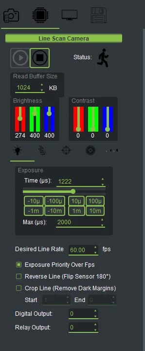
Crop Line on line scan cameras
In the line scan USB cameras, in the Exposure tab, you will find the Crop Line (Remove Dark Margins) option. When you enable it, only pixels Start to End of each line are kept.
The important point is that cropping is not just for display. It happens at the source, where the camera data is interpreted. So the line plot, the image and the saved file are all genuinely smaller. The processor and disk get some breathing room too.
A few rules about the numbers:
- Numbering starts at 1, and Start and End themselves are included in the kept section.
- If you set End to 0, it means "up to the last pixel".
- While cropping is off, these two fields are disabled.
- Open the line intensity plot (Line Scope) and put the object or a bright surface in front of the camera.
- Zoom into the bright part of the plot and read the pixel numbers where it starts and ends from the horizontal axis.
- Enter these two numbers in Start and End, and turn on Crop Line.
Another way is to select a vertical strip on the image in the Advanced Scanner Scope display; the Start field fills in automatically. Then check End as well.
To confirm, look at Pixels H in the diagnostics panel. After cropping, this number should be smaller than the full sensor width.
Sometimes mechanical constraints do not let you mount the camera in the direction you want, and the image comes out mirrored left to right. The Reverse Line (Flip Sensor 180°) option mirrors each line horizontally at the source. That is, the first pixel takes the place of the last, as if the sensor had been rotated 180 degrees. Because this happens at the source, all downstream nodes receive the correct data. It is off by default.
If you turn on Reverse Line and Crop Line together, their order is fixed: the line is reversed first, then cropped. So if you read Start and End before turning on Reverse Line, check them again.
In area scan cameras USB cameras, the Image Data page of the camera panel has a section called AOI. With it, only a rectangle of the sensor is read. Define the rectangle by its starting row and column (Start) and its size (Size). Then send it to the camera with Send Cmd. A smaller AOI produces less data and can increase the frame rate.
You do not need to calculate the numbers by hand. Select the region with the mouse on the image display, and the AOI fields fill in automatically.
There is one subtlety. If the image you select on has already been cropped with an AOI, the selection coordinates are relative to that cropped image, not the full sensor. The + Last button fixes this: it adds the starting point of the last AOI sent to the numbers so they are correct relative to the full sensor again. To return to the full image, press Send Reset Cmd.
The Mirror section on the same page has two buttons. Vertical flips the image top to bottom inside the camera itself, and Horizontal flips it left to right. Both turn off again on every Start.
- Cropping too tightly. If the object shifts slightly on the belt, its edge falls outside the image. Leave a margin of a few pixels.
- Cropping before the final exposure setup. The correct order is: first set Exposure. Then set brightness and contrast with Brightness and Contrast. Finally, move on to Crop.
- Using calibration files made with the full line width. After the data dimensions change, these files no longer match the new stream and must be recreated.
To learn more about the region of interest (ROI), Wikipedia article (English).
If you are not sure whether line cropping is enough for your job or you need a different sensor, talk to us.